


DSP-Based Pulse Detection
- Overview
- Use of SHARC DSP Board in Pulse Detection System
- Use of DirectCore® Software in Pulse Detection System
- DSP C Code Example
- For More Information
- Return to DSP Applications Page
 Visual Basic (VB6) Example 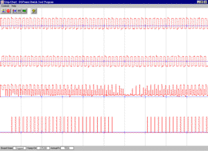 Visual C/C++ (Visual Studio 6.0) Example |
Overview
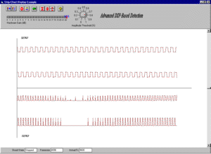
Pulse detection is a commonly employed algorithm in systems that use a dual set of input transducers producing dual sets of signals that must be analysed. The use of duality is well-known in natural systems, obvious examples are human vision and hearing. In machine detection it is also widely utilized; typically by placing two (2) transducers slightly offset from each other either spatially or temporally. Such a system can detect more information about its surroundings than a single-transducer system, and because it relies on the basic idea of subtraction, it is also more immune to noise and interference. Pulse detection is used in a wide variety of industrial processes and applications, including machine sensing, chemical and metal detectors, magnetic and electrostatic field based detectors, and more. After subtraction, or "exclusive OR" in some systems, a raw difference waveform results which must then be further processed to extract individual pulses and/or statistical measurement of pulses. In order for results to be useful the algorithm performing the processing must be flexible, dynamic, accurate and reliable. Signalogic uses digital signal processing (DSP) to manage and modify input signals which have originated in analog form from the dual transducers. Signalogic's DSP-based Pulse Detection System (PDS) detects differences between two signal inputs, and can be used on a wide variety of DSP/data acquisition boards that either plug into PCs or operate stand-alone. The PDS algorithm first calculates a 3rd trace as an difference, and then a 4th as filtered, or smoothed, output. Actual pulses that meet certain width and threshold requirements specified by the host operator interface are recorded on a fifth trace (see examples of output on left).Use of SHARC DSP Board in Pulse Detection System
|
|
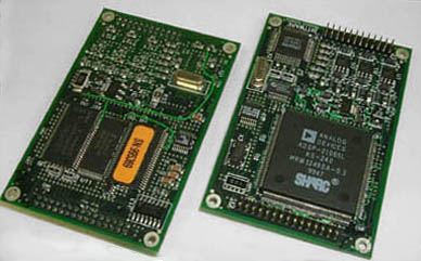
SHARC DSP Board, with 40 MHz 21065 processor, 4M SDRAM, 2/6 channel 16-bit sigma-delta audio I/O Click to see full size picture |
Use of DirectCore® Software in the Pulse Detection System
The DirectCore® software ◳ provides an interface layer between the PDS algorithm and host applications, for example Microsoft Visual C/C++ or Visual Basic (as in the examples shown above), MATLAB, and LabVIEW. Using this software, the host application can:
- set up and control the DSP/data acquisition board, including downloading DSP executable code
- communicate with the DSP code while it runs in real-time; this includes monitoring the code to update gauge and instrument displays, uploading raw and/or processed waveform data, and sending new parameters to the DSP code to cause its operation to change dynamically
- measure performance of the algorithm and adjust to maintain real-time operation
DSP C Code Example
Below is simple example in C code that runs on a DSP in real-time and demonstrates how the DSP Source Code Interface (SCI) software product can be used as the framework for creating real-time algorithms that run on DSPs and can be wholly implemented in C code. Note that the DSP SCI takes care of initializing host application-specified properties and parameters, hardware and DSP setup, analog I/O setup, communicating with the host interface during operation, sample interrupts, real-time input and output buffer handling, and all other processing required to ensure continuous data flow. The function PulseDet() is called when each new buffer of analog input data is ready. The size of each buffer is the "framesize" in samples, which can range from 1 sample to 32k or more, depending on the size of time segments that should be processed by the algorithm. The choice of framesize depends heavily on the nature of the data and algorithm; for example a speech processing algorithm might use a framesize equivalent to 12 msec, because speech tends to stay "quasi-stationary" for 10-15 msec before changing significantly. The framesize is another property that can be specified from the host application program. More C code processing can be added as needed, and more or less output buffers used. Note that by convention if nNumTrace > 1, then data is stored as interleaved values, in repeating groups of nNumTrace values. For example, tr0,tr1,tr2,tr0,tr1,tr2, ... for 3-trace acquisition. Also note that traces can be mapped to any physical channel on the DSP/data acquisition board, depending on the CHANNEL LIST property specified in Hypersignal software or host application software (i.e. C/C++, Visual Basic, or MATLAB software using the DirectCore interface. For more details about user-defined real-time C code, see also DSP Coding Workshop and Adding User-Defined Real-Time C Code.-
void PulseDet(void* ptrIn, void* ptrOut, long nLen, long nNumTrace) {
#define x ((long*)ptrIn)
#define y ((long*)ptrOut) extern float AmpThreshold;
extern int thresh_sum;
extern int RunLen;
extern long PulseWidth;
extern float FilterGainFactor;
extern float NoiseFloor;
extern float DigScaleFactor;
extern int Save[]; #define SaveLength 20
#define thresh_pulse 50 int n,nIndex,j,k,sum,pulse_count, pulse_visible; float thresh;
pulse_count = 0;
pulse_visible = 0;
for (n=0; n<nLen; n++) { nIndex = nNumTrace*n; /* show traces 0 and 1 as raw data */ x[nIndex] = DigScaleFactor*x[nIndex];
if (nNumTrace > 1) {
x[nIndex+1] = DigScaleFactor*x[nIndex+1];
}
/* bias trace 1 and 2, subtract trace 1 from trace 0, show as trace 2 */ if (nNumTrace > 2) {
x[nIndex+2] = abs((x[nIndex] + 32768) - (x[nIndex+1] + 32768));
} /* update very long-term average */ thresh_sum = FilterGainFactor*x[nIndex+2] + (1-FilterGainFactor)*thresh_sum; /* apply running sum pulse filter, show as trace 3 */ sum = 0;
k = SaveLength-1; for (j=0; j<RunLen; j++) {
if ((n-j) < 0) sum += Save[k--];
else sum += x[nNumTrace*(n-j)+2];
}
sum >>= 3; if (sum > AmpThreshold*thresh_sum + NoiseFloor) { if (nNumTrace > 3) x[nIndex+3] = 10000; // pulse = 1
pulse_count++; }
else { if (nNumTrace > 3) x[nIndex+3] = 0; // pulse = 0 if (pulse_count > PulseWidth) { if (nNumTrace > 4) x[nIndex+4] = 10000;
pulse_visible = 20; // arbitrary pulse width; just needs to be visible
}
pulse_count = 0; }
// extend pulse; make sure visible on screen
if (pulse_visible > 0) {
if (nNumTrace > 5) x[nIndex+4] = 10000;
pulse_visible--;
}
else if (nNumTrace > 5) x[nIndex+4] = 0;
}
// save end of each frame for use with next frame for(n=nLen-1; n>=(nLen - SaveLength); n--) { nIndex = n*nNumTrace;
Save[SaveLength-(n-nLen)] = x[nIndex+2];
}
} // end of function /* C Code Notes: 1) y is output; i.e. output coming out of board (for example, speaker) 2) x is input; i.e. going into board; for example pulse generator 3) Both x and y are interleaved; i.e ch0,ch1,ch2...,chN-1 where N is the
number of channels. 4) if you modify x traces, you see it in the host display 5) if you modify y traces, you only know it if you look at the board's output */
For More information About Pulse Detection...
For more information on DSP-based Pulse Detection System please send mail to:-
email to: dspinfo (at) signalogic.com