DSPower® Software Technical Information
No longer available; please
click here for other DSP
software.
DSPower® Visual Environment software v3.0 is a DSP product, system, and algorithm design
software package which runs under Win9x, or WinXP. The package presents
an integrated user-interface which offers block diagram signal flow editing, source
code editing, DSP and math function blocks, user-defined function blocks, and
real-time code generation and debug for more than 80 types
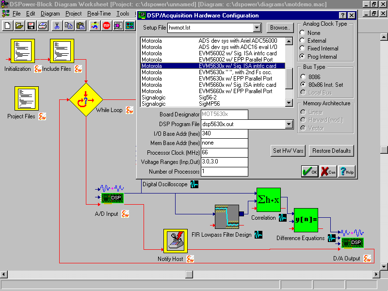
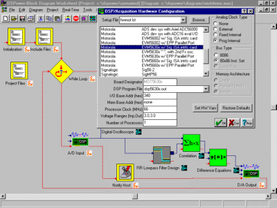
of off-the-shelf DSP/data acquisition hardware. In addition, DSPower Visual
Environent software provides interactive data visualization displays and instruments
blocks, allowing users to debug designs, perform in-depth analysis, and make analog
signal measurements.
DSPower software can manipulate, save, and generate three types of source code, two for
simulation purposes, and one for real-time systems. For simulation of block diagrams, DSPower
generates MATLAB® (.m) and Hypersignal® macro language (.mac) code and saves diagrams directly
in these formats. For real-time systems, DSPower generates C/C++ (.c or .cpp) code, and
saves diagrams in C/C++ source code format. Generated
MATLAB and Hypersignal source code can be used to perform algorithm or system
simulation, and generated C/C++ language source code can be downloaded for
real-time execution on a supported board. To some extent, block equivalence is
maintained across source code types, allowing a diagram first to be
simulated with MATLAB or Hypersignal macro language blocks (or combination), and then
regenerated as C source code for real-time execution.
Creating user-defined functions is well-supported and possible using methods
which do not require programming knowledge. A graphical "block wizard" is available to
assist in creating user-defined block symbols, defining block inputs, outputs, and other
setup properties, and assigning user-defined source code to new blocks.
Algorithm, System, and Product Simulation
Diagram Execution. Block diagram execution is data-driven by default;
however, all blocks contain optional control connections which can be used to explicitly
specify execution sequences. Control-flow may also be specified for
ambiguous situations and is required for control construct blocks such as loops,
if-then, and case-statement. Individual blocks or groups of blocks can be isolated and
run as "partial execution" without disturbing the overall diagram.
Simulation Mode. In simulation mode, the block diagram and associated
source code files are executed on the host PC. In simulation mode, generated code is
compiled and executed by the applicable DSP engine, either Hypersignal-Macro or
MATLAB. Simulation block diagrams may reference blocks which are external DLLs,
OCX, or ActiveX objects, in which case the generated Hypersignal or MATALB code invoke
these blocks at the appropriate location in the diagram execution flow. All intermediate
results are stored in time, frequency, or wavelet domain waveform files, allowing
post-simulation analysis and debug at any point in the diagram.
Real-Time Mode. In real-time mode, the block diagram and associated
source code files are compiled (and assembled), linked, and downloaded for execution
on a supported DSP/data acquisition board. Real-time diagrams may reference
intermediate result storage or display blocks, such as "probe-point", debug, or utility
functions.
Probe-Point and Debug Blocks. In real-time mode, probe-point and debug blocks
may be added to diagrams, including text readout, monitors and gauges, and waveform
displays. Probe-point and debug blocks are normally "tied" to a symbol or variable name
in the generated real-time code, although they can also access absolute onchip or external
SRAM locations. For synchronous probe-point and debug blocks, constructs are embedded in
the generated real-time C code
which cause the DSPower host software to upload time or frequency domain data from the
DSP/data acquisition board and display it in the appropriate window, store it to file,
etc. For "asynchronous" probe-point and debug blocks, which are not necessarily connected
to other blocks in the diagram, an update rate must be specified (in msec). For all
probe-point and debug blocks, unlike JTAG-based debugging, the DSP/data acquisition board
is accessed as the real-time code continues to execute, without stopping.
User-Interface
Signal Flow Editor. The DSPower signal flow editor offers a
graphical, object-oriented block diagram interface, including graphical block
symbols, data-flow and control-flow interconnections between blocks, block setup
property dialog boxes, and Block Selector which organizes and categorizes block libraries.
Source Code Editor. The DSPower source code editor allows multiple files to
edited at one time, highlights keywords for three
(3) different source languages (C, MATLAB, and Hypersignal macro language), and is
integrated with the signal flow block diagram editor. For example, source code files
associated with blocks can be easily located and edited by clicking on block parameters,
including file names, connections, and function names.
Multiple Project Interface and Multiple Diagram Interface. The DSPower
user-interface includes multiple project support and multiple diagram support. Users can
maintain different projects to accomodate simultaneous development efforts and different
DSP/data acquisition hardware configurations. Each project supports multiple signal flow
diagrams and multiple source code files being viewed and edited at the the same time.
Worksheet Objects. Worksheet objects include Block Selector,
toolbars, multiple diagram and source code file interface, DSP/analog hardware setup and
configuration, simulation and real-time mode setup and configuration, and
waveform file locator.
Block Selector. A Block Selector is used to present the current configuration
of block libraries onscreen. Block categories include code, control construct,
function, display and visualization, filter, instrument, utility, and debug/monitor.
A configuration utility is available to allow the Block Selector to be configured
online. Blocks can easily be listed and unlisted from the current Block Selector
display, renamed, and deleted. Blocks may be moved between libraries and appear in more
than one library simultaneously. User-defined blocks may be manipulated as easily as
system blocks.
Interactive Display and Instrument Blocks. Display and
instrument blocks can be shown and arrayed in various sizes; maximize and
automatic tiling options can be used to temporarily utilize worksheet area
for detailed display/instrument analysis and measurement.
Block Setup Properties. Block setup properties include inputs, outputs,
and operating parameters. In many instances, blocks contain both
standard and "Ex" setup properties. These parameters can be set prior to
diagram execution or individual block interactive operation. For example, a typical FFT
block contains input, output, and FFT size as standard properties; additional
Ex parameters include window type, overlap, and analysis framesize
(zero-fill). If Ex properties are present but not specified, default values are
used. Setup properties for individual blocks are saved according to
block type and/or waveform file input.
Online Help. Dialog box fields, controls, and other
user-interface objects in the DSPower environment have context-sensitive online
help text available. Context-sensitive online help can be invoked by right-clicking
on the user-interface object, using the main Help button in dialog boxes, or in most cases,
stabilizing the cursor over the object to cause fly-over help text (sometimes referred to
as "hint" or "tooltip" text) to appear.
When context-sensitive help text is displayed, an additional "small help" button is often
present which can be used to display more detailed online help documentation
sections.
All dialog boxes and worksheet objects such as the Block Selector contain Help
buttons. Important sections of online documentation are available from the main menu
Help item.
Interactive Operation
Access to Waveform Analysis and Function Results. Blocks
can be run individually and as partial diagrams. Each block contains an
"Run" button, which activates the function or display/instrument using the
currently entered setup properties. For display and instrument blocks, all
interactive measurement and analysis controls are active. In simulation mode,
intermediate results are stored in waveform files, which can be displayed and
analyzed using interactive display and instrument blocks.
User Control Objects. Display and instrument blocks include a
rich assortment of interactive controls. Examples include:
zoom, pan, amplitude offset and control
waveform editing (cut-paste and rubberband)
D/A output to supported DSP/analog hardware
multitrace and overlay options
256-color contour frequency domain displays, with fast
update, control over dB range and step, time-spanned, and zoom/pan
linear and log amplitude formats; linear and log axes
in frequency domain displays
cursor readout and measurement
display format, axes, grid, plot style, and many other options
context-sensitive online help
User-Defined Expansion
Adding user-defined blocks. Blocks can be easily added in the DSPower system
by specifying a template file and one or more associated code files (functions, include
files, library files, etc.). A graphical "block wizard"
is available which generates block template files, using existing blocks as a starting
point or creating new blocks from scratch. The block wizard allows block
symbols, inputs, outputs, and other setup properties, and associated source code to
be defined graphically.
Once a template file has been created for a new block, the block can be added to one or
more user libraries using the configuration utility for the Block Selector (see above).
Template Files. All blocks are "registered" in the DSPower system
by a unique template file which contains all block properties. Properties include
graphical symbols, inputs, outputs, operating (setup) parameters, associated code,
attributes, data types supported, and interactive user-interface controls, if
any. All aspects of block definition are specified in the template file, and may
be user-defined, including the type and layout of interactive toolbars, dialog boxes,
and other user-interface objects.
Associated Code Files. Each block typically has associated with it one or
more code files. Code files may specify functions (in source or object form), "include"
files, and library files.
DSP Engines
Central to the design of DSPower software is the capability to perform both simulations and
real-time code operation. To allow this, the concept of "DSP engines" is used, which
creates a clear division of labor between visual representation and source code
generation on one side and compilation, link, and execution of generated code
on the other. The DSPower Visual Environment software is responsible for all required
user-interface, including signal flow diagram and source code editing and visual IDE,
code generation and all support functions, and Windows interface. DSP engines
are responsible for code execution.
The line blurs somewhat in two cases:
1) When running interactive display and instrument blocks in order to perform signal
measurement and analysis. This typically involves generating temporary code for one
block, and invoking the appropriate engine.
2) When generated code for a block diagram is executing, because probe-point,
debug, monitor/gauge, and display blocks must be updated inside the visual environment
according to execution flow in the diagram, and based on information sent by the
DSP engine. To accomplish this, DSPower software uses
asynchronous communication methods to transfer data independently of executing
code. Examples include VxD drivers, kernel mode drivers, and hardware drivers
in the case of DSP/data acquisition boards.
In simulation and interactive display and instrument modes, the MATLAB and
Hypersignal-series (-Macro, -Macro Ex, and -Acoustic) engines provide excellent
capability, by virtue of their rich procedural languages, built-in compilers,
numerous DSP and math functions and waveform displays, and in the case of Hypersignal,
driver support for more than 80 types of
DSP/data acquisition boards.
System Requirements
DSPower Visual Environment software requires Win9x, or WinXP,
and at least a 33 Mhz 80386 machine with 4 Mb or more of memory.

|